Missing terminal pins in wiring harness connectors are one of the canonical escape defects in automotive assembly. The reason they escape so reliably is that a connector with a missing pin will often pass a continuity test at the harness assembly level — the missing circuit simply doesn't complete, and if the test fixture doesn't cover 100% of expected circuits, the absence goes undetected. The defect then travels through sub-assembly, vehicle assembly, and final functional test, emerging as a warranty claim after the vehicle is in the field.
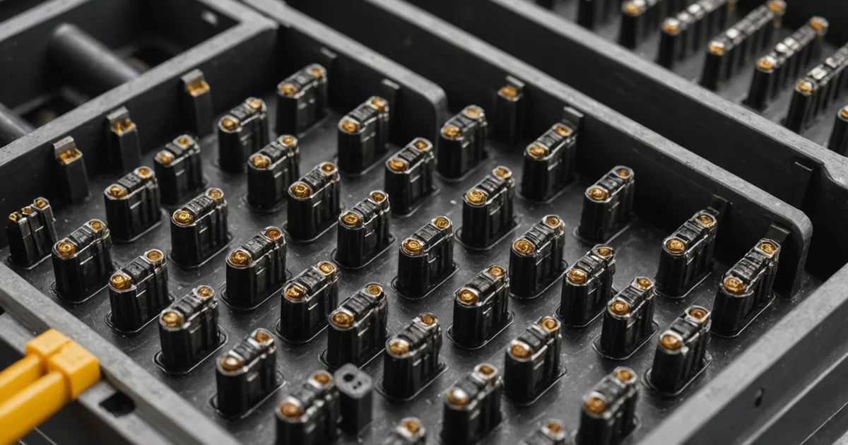
The detection physics are also challenging. A correctly populated multi-pin connector presents a regular grid of metal terminal tips visible when viewed from the mating face. A missing pin presents an empty cavity — a dark hole where a metal surface should be. The contrast difference between a present pin (specular reflection from the terminal tip under inspection lighting) and an absent pin cavity (dark, non-reflective) is actually quite large. The challenge isn't the contrast; it's the spatial resolution and positioning repeatability required to reliably locate and classify every cavity in a 24- or 36-pin connector at the throughput rates typical of wiring harness assembly.
Why this problem is harder than it looks
A typical mid-sized automotive connector — say, a 24-position Delphi GT series or equivalent generic housing — presents its terminal cavities in a 4×6 grid with a 5mm pitch between cavity centers. At 1280×1024 resolution with a standard 1/2" GigE camera at 200mm working distance and a 25mm lens, each cavity occupies roughly 8×8 pixels in the image. That's enough resolution to distinguish a present terminal (bright spot with specular highlight) from an absent cavity (dark), but it's near the lower limit for reliable detection.
The harder problem is positional consistency. Wiring harness assembly is manual — operators insert individual terminals one at a time. The finished connector housing reaches the inspection station with slight positional variation depending on how the operator placed it in the fixture. A 2mm lateral variation in connector position shifts the cavity grid by nearly half a pixel pitch at this imaging geometry. If the model was trained to expect cavities at fixed pixel coordinates, that variation produces false positives and false negatives even with perfect contrast.
The solution isn't tighter fixturing (though that helps). It's a detection approach that dynamically locates the connector housing boundary first, then searches for terminal presence/absence relative to the detected housing geometry — not relative to fixed image coordinates. This is what makes the pin absence problem a model architecture question, not just a resolution question.
The detection approach: localize first, then classify
Procunit handles pin absence detection through a two-stage inference pipeline. The first stage runs a coarse localization model that finds the connector housing boundary and reference features (housing edge, polarizing key, or first/last cavity position) in the image. The second stage warps the image to a canonical connector orientation and then classifies each cavity position independently.
The canonical orientation warp is a projective transform calibrated to the specific connector part number. For a 24-position connector with a known cavity grid, the warp maps the detected housing to a standard 1:1 pixel representation where each cavity occupies a fixed image region. The cavity classifier then runs on each of the 24 fixed regions and produces a present/absent label for each.
Training data requirements for this approach: you need labeled examples at the canonical orientation level, not the raw image level. For a connector type being added to the inspection model, we collect approximately 40 to 60 raw images with known good configurations (all 24 positions populated), 20 to 30 images with each of the common missing-pin positions (which tends to be the first few positions inserted, as these are the most frequently left incomplete when an operator is interrupted), and 10 to 15 images per unusual failure mode (bent pin, partially retracted terminal).
The localization model is part-agnostic — it works on any connector housing without retraining. The cavity classifier is trained per connector part number. For a wiring harness assembly line running 4 to 6 different connector types, we typically see training datasets of 300 to 400 images across all variants, with training completing in 6 to 8 hours on the standard IPC configuration.
Illumination for terminal tip detection
Terminal pin detection benefits from coaxial illumination at relatively low working distance. The goal is to produce specular reflection from the metal terminal tip while keeping the cavity background (the inside of the empty housing cavity) dark. Coaxial illumination — where the light travels along the optical axis — achieves this by matching the reflection angle of the flat terminal tip face to the camera's line of sight.
Ring lights at oblique angles (typically used for general surface inspection) work poorly for terminal tip detection because the off-axis illumination creates specular reflections on the housing walls and connector housing surface that compete with the terminal tip signal. At oblique angles, even populated cavities can show reduced tip contrast because the terminal tip reflects light away from the camera rather than toward it.
For a 24-position connector at the geometry described above, we use a 40mm coaxial ring with a beam splitter, mounted 180mm above the inspection fixture. The ring diameter is matched to the connector face area to avoid edge lighting effects. The strobe pulse width is 250 microseconds, timed to the frame capture trigger from the line PLC.
One practical challenge on harness lines: metal terminal tips produce bright specular reflections, but so do metallic debris particles — metal shavings from terminal insertion crimping, aluminum housing flash, or copper strands from wire ends. A false positive from debris is more likely on a harness line than on a machined parts line because of the quantity of metallic material in the immediate environment. Including training examples with debris present in empty cavities helps the model distinguish the signal (terminal tip geometry and size) from debris (irregular shape, off-center position in cavity).
Cycle time and throughput
A 24-position connector inspection at 180 ppm means one connector every 333 milliseconds. The full two-stage inference pipeline — localization plus 24-cavity classification — runs in approximately 11ms on the i7-12700 IPC. Including frame capture trigger, image transfer via GigE, and PLC signal output, total latency is under 18ms. At 333ms per connector, there's substantial headroom.
Where harness lines get more complex is multi-connector harnesses — a single harness assembly may have 8 to 12 connector positions, and some lines present the full harness at an inspection station rather than individual connectors. For multi-connector inspection in a single frame, the camera resolution requirement scales with the number of connectors being imaged simultaneously. For more than 3 to 4 connectors per frame, a higher-resolution sensor (5MP or 9MP) becomes necessary to maintain adequate pixels-per-cavity across all connector positions.
We've run multi-connector setups with two cameras — one covering each half of the harness — triggered synchronously and processed in parallel on the IPC. Inference on both camera streams adds approximately 8ms to the total pipeline latency, keeping the combined inspection within 30ms. Both cameras share the same PLC interface; the reject signal fires if either camera flags a missing pin.
What vision inspection doesn't replace: final circuit check
Visual inspection for pin presence confirms that a terminal is physically present in its cavity. It does not confirm that the terminal is correctly crimped onto its wire, that it's locked into the housing retention feature (fully seated), or that it's making good electrical contact. A terminal that's present and visible but not fully locked can still result in intermittent circuit failure in the field.
We're not saying visual inspection replaces electrical continuity test or terminal lock-detect force testing. On lines where the downstream functional test covers full circuit continuity, visual inspection is most valuable for the defects that functional test misses: missing terminals in circuits that functional test doesn't cover, or terminals present in the wrong cavity position (visually present, electrically incorrect). For high-confidence quality on critical harnesses, visual inspection and electrical test are complementary, not substitutes.
The practical case for visual inspection at the harness assembly level is that it provides per-cavity spatial resolution that electrical test doesn't. A functional test can confirm that all circuits pass; visual inspection can confirm that every cavity has a terminal and no terminals are present in incorrect positions. The combination of both gives you a more complete quality picture than either alone.
On the harness lines we've deployed on, visual inspection catches approximately 85 to 90% of missing-pin defects at the point of assembly — before any wiring or secondary operations are added to the harness. The remaining 10 to 15% of missing pins are caught by the downstream electrical test. The value of the inline visual stage is catching them early enough that the harness hasn't yet been bundled, laced, and cut to length — work that all has to be undone if a missing pin is found at final test.